Product overview
- Part Number
- Seeeduino Stalker V3.1
- Manufacturer
- Seeed Studio
- Product Category
- OTHER PARTS
- Update Date
- 2024-05-20
Detailed Information
Maybe you are very familiar with the seeeduino stalker series, or maybe you are totally new to this feature rich Wireless Sensor Network Node. No matter what situation you are in, if you are going to make an outdoor data-logging application, you will find that Seeeduino Stalker is the best board.
The main purpose of creating this series is to create an X-bee carrier board so that users can make outdoor application more conveniently. Ever since the first version be released in 2009, Seeeders have been continuously collecting feedback from users and kept upgrading the board. there are 6 versions ever existed during the past 7 years, this summer we are excited to release the most updated member of the Seeeduino stalker family–Seeeduino Stalker V3.1.
Seeeduino Stalker V3.1 is not just a simple update of V3.0. The main surprise you’ll find about the board is impressively low power consumption, in sleep mode, the output current of the whole board will be as low as 100uA,the mian reason for this progress is that in V3.1, when MCU is in sleep mode, all other power supplement, including Bee area port, 3.3v port, VCC can be cut off manually, so that power can really be saved.
Changes from the Stalker V3.0
There is a toggle switch added to X-bee area, which allows you to select either the hardware serial port or software serial port base on what you want to connect.
We also added 2 toggle switch on RTC circuitry corresponding 2 INT pin of MCU, so that users can easily choose which INT pin to be connected with RTC INT port then activate MCU.
Just like every other revises, we fixed a few bugs.
Specifications:
Arduino compatible, based on Seeeduino
MCU: ATmega328P
RTC powered by button cell only
2 toggle switch on RTC circuitry
Serial interface with DTR for auto reset during programming when operating in standalone mode.(For programming, UartSBee must be bought separately)
Bee series socket – 2*10 pin 2.0mm pitch (which will mate with – one at a time – any of the wireless modules: X-Bee, Bluetooth-Bee, GPS-Bee or RF-Bee.)
1 toggle switch on Bee socket
Micro-SD card socket
I2C Pin header (operation voltage is selectable: 5.0V or 3.3V)
User defined LED
Current in sleep mode:<100 uA
Size of PCB:86.1mm x 60mm
Note:
Please set D0,D1 as input before going into sleep mode
Please turn on the power before using Bee, grove port, 3.3v and 5v port
The IO Ports work in 0~3.3v level only
Documentation:
Please visit the Wiki page for more information about this product. It will be much appreciated if you can help improve the documents, add more demo codes or tutorials. For technical support, please post your questions to our Forum.
Price & Procurement
Associated Product
-
-
-
-
-
-
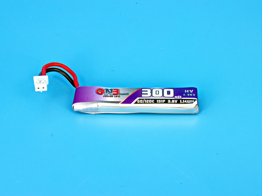
Capacity: 300 mAh Nominal voltage: 3.8 V Maximum discharge current: 60C ...
-
DarkStar20: So light, it makes feathers look overweight. Perfect for sneaking th ...
-
With 20A Blheli_s ESCs and an integrated ELRS RX, this FC lifts your drone’s per ...
-


